Sunday, November 16, 2025

Proxmox. Installation and first steps after

 Installation

  1. Create bootable USB.
    Prepare Installation Media
    For Windows it could be Rufus. ISO can find on official Proxmox site Proxmox ISO.
  2. Boot from USB and start Proxmox installation wizard GUI or Console.
  3. Install Proxmox.
    Wizard is very simple. For example here is manual with screenshots How to Install Proxmox VE 9 Detailed Guide
  4. Installation options.
    I changed only few options:
    • set static IP
    • set hostname
    • set home DNS domain
    • set filesystem as XFS
    • set root filesystem size 30G
  5. That's all.
First steps after installation
  1. Disable enterprise update repository and enable No-Subscription version.
    • In Proxmox GUI  go to Updates -> Repositories.
    • Select repository with Component: pve-enterprise and click Disable.
    • Click Add button, in Repository select "No-Subscription" and click Add.
    • Click Add button, in Repository select "Ceph Squid No-Subscription" and click Add.
  2. Update Proxmox.
    • In Proxmox GUI  go to Updates
    • Click Refresh. Wait until all repositories will be checked and close dialog window.
    • Click Upgrade. New console window will be opened. Wait until you see question "Do you want to continue? [Y/n]", confirm update process (press Y). 
    • Wait until all updates will be installed. You will see message "Your System is up-to-date". Close console window.
    • Check updates few times. Until you see message "No updates available" in Proxmox GUI -> Updates.
  3. Enable PCI Passthrough
    First Steps After Installing Proxmox 8: A Comprehensive Guide
    If your hardware supports PCI passthrough, you can enable it.
    • Edit the grub configuration:
      vi /etc/default/grub
    • Comment out the line:
      GRUB_CMDLINE_LINUX_DEFAULT="quiet"
    • Add this line instead:
      GRUB_CMDLINE_LINUX_DEFAULT="quiet intel_iommu=on iommu=pt"
      For AMD, replace “intel” with “amd.”
    • After editing, update GRUB:
      update-grub
    • Next, add Virtual Function I/O modules to /etc/modules:
      vi /etc/modules
    • Add the following lines:
      vfio
      vfio_iommu_type1
      vfio_pci
    • Save your changes and reboot your server.
      reboot now
  4. Storage Configuration
  5. VLAN Configuration
    First Steps After Installing Proxmox 8: A Comprehensive Guide
    After your server reboots, you can configure VLAN support in the Proxmox web UI:
    • Select your server.
    • Go to “Network” in the menu.
    • Select the Linux bridge (vmbro#).
    • Click “Edit” at the top of the window.
    • Check the box that says “VLAN aware.”
    • Press “OK.
  6. Create Proxmox admin user
  7. Disable Subscription Popup
    To remove the subscription popup, run the following command:
    sed -Ezi.bak "s/(Ext.Msg.show\(\{\s+title: gettext\('No valid sub)/void\(\{ \/\/\1/g" /usr/share/javascript/proxmox-widget-toolkit/proxmoxlib.js && systemctl restart pveproxy.service

    Afterward, reboot your server, log out of the Proxmox web GUI, clear your browser cache, and then log back in.
  8. Run Proxmox post install community script
    https://github.com/community-scripts/ProxmoxVE/tree/main
    https://community-scripts.github.io/ProxmoxVE/scripts?id=post-pve-install&category=Proxmox+%26+Virtualization
    Post install script replace steps 1 and 7.

Friday, January 17, 2025

Ubiquiti ER-X router configuration

Sources:

https://gist.github.com/pinkeen/3076cd6f5cc5b08d3faacfa2db149a17
https://www.vanwerkhoven.org/blog/2022/home-network-configuration/
https://justinho.com/blog/2020/09/03/cleanedgerouter.html
https://loganmarchione.com/2016/04/ubiquiti-edgerouter-lite-setup/
https://help.ui.com/hc/en-us/articles/218889067-EdgeRouter-How-to-Create-a-Guest-LAN-Firewall-Rule
https://help.ui.com/hc/en-us/articles/360002231373-EdgeRouter-How-to-Find-the-Base-MAC-Address

We define the following networks:

  • WAN - WAN interfaces
  • LAN - VLAN 1 (U) - 192.168.10.0/24 - all trusted hosts (PCs, smartphones, tablets, TVs, homeassistant etc) - router, switch
  • Guest - VLAN 20 (T) - 192.168.20.0/24 - guest wifi
  • IOT - VLAN 30 (T) - 192.168.30.0/24 - smart devices
  • DMZ

We define the following zones:

  • WAN: internet
  • LOCAL: router (er-x.matrix.local), dns, dhcp, switch (usw.matrix.local), wifi (u7ap.matrix.local)
  • LAN: trusted network, all wired and wireless hosts, home server (homeassistant, ha.matrix.local) serving http(s), ssh, mqtt, and many more
  • GUEST: untrusted network allowed to connect to internet
  • IOT: untrusted network allowed to connect to the home server (homeassistant, ha.matrix.local) and IOT cloud hosts
  • DMZ: reverse proxy (not defined yet) for home server (homeassistant, ha.matrix.local)

Firewall rules:

---to WANto LOCALto LANto GUESTto IOTto DMZ
WAN-wan_to_allwan_to_allwan_to_allwan_to_allTDB
LOCALfw_accept-fw_acceptfw_acceptfw_acceptTDB
LANfw_acceptfw_accept-fw_acceptfw_acceptTDB
Guestfw_acceptguest_to_localguest_to_lan-fw_dropTDB
IOTiot_to_waniot_to_localiot_to_lanfw_drop-TDB
DMZfw_acceptfw_acceptfw_acceptfw_dropfw_drop-

Keep last 10 configuration commit revisions (by default none is kept)

See the official docs for verbose info.

set system config-management commit-revisions 10

This allows you later list commits and roll them back.
After fuckup rollback to specific revision\

rollback ? # list commits
rollback {NUM}

Harden services

set service gui listen-address 10.0.0.1
set service gui older-ciphers disable
set service ssh listen-address 10.0.0.1
set service ssh port 22
set service ssh protocol-version v2

Connect to UISP matrixx.uisp.com

https://help.ui.com/hc/en-us/articles/115012196527-UISP-First-Time-Setup-Installation

Install SSL from Let's Encrypt

https://github.com/j-c-m/ubnt-letsencrypt
https://thehomeofthefuture.com/installation-guide/set-up-an-ubiquiti-edgerouter-from-scratch/

# Get current configuration
show configuration commands

configure
set system conntrack expect-table-size 4096
set system conntrack hash-size 4096
set system conntrack table-size 32768
set system conntrack tcp half-open-connections 512
set system conntrack tcp loose enable
set system conntrack tcp max-retrans 3
set system analytics-handler send-analytics-report false
set system crash-handler send-crash-report false
set system host-name er-x
set system login user simsim authentication encrypted-password '$5$GzaxeALmDwwUVsIn$1.8BstbMd7IHI23lILPW2Nt/EITe4e0cpBrxA31cYaD'
set system login user simsim level admin
set system ntp server 0.ua.pool.ntp.org
set system ntp server 1.ua.pool.ntp.org
set system syslog global facility all level notice
set system syslog global facility protocols level debug
set system time-zone Europe/Kiev
set system offload hwnat enable
set system offload ipsec enable
set system domain-name home
set system systemd journal
set system traffic-analysis dpi enable
set system traffic-analysis export enable
set service gui http-port 80
set service gui https-port 443
set service gui older-ciphers disable
set service ssh port 22
set service ssh protocol-version v2
set service unms disable
set service ubnt-discover disable
commit; save; exit
reboot now
configure
set firewall all-ping enable
set firewall broadcast-ping disable
set firewall ipv6-receive-redirects disable
set firewall ipv6-src-route disable
set firewall ip-src-route disable
set firewall log-martians disable
set firewall receive-redirects disable
set firewall send-redirects enable
set firewall source-validation disable
set firewall syn-cookies enable
set firewall group network-group PRIVATE_NETS network 192.168.0.0/16
set firewall group network-group PRIVATE_NETS network 172.16.0.0/12
set firewall group network-group PRIVATE_NETS network 10.0.0.0/8
set firewall modify balance rule 10 action modify
set firewall modify balance rule 10 description 'do NOT load balance lan to lan'
set firewall modify balance rule 10 destination group network-group PRIVATE_NETS
set firewall modify balance rule 10 modify table main
set firewall modify balance rule 50 action modify
set firewall modify balance rule 50 description 'do NOT load balance destination public address'
set firewall modify balance rule 50 destination group address-group ADDRv4_eth3
set firewall modify balance rule 50 modify table main
set firewall modify balance rule 60 action modify
set firewall modify balance rule 60 description 'do NOT load balance destination public address'
set firewall modify balance rule 60 destination group address-group ADDRv4_eth4
set firewall modify balance rule 60 modify table main
set firewall modify balance rule 70 action modify
set firewall modify balance rule 70 modify lb-group G


set load-balance group G exclude-local-dns disable
set load-balance group G flush-on-active enable
set load-balance group G gateway-update-interval 20
set load-balance group G interface eth3
set load-balance group G interface eth4
set load-balance group G lb-local enable
set load-balance group G lb-local-metric-change disable
set load-balance group G exclude-local-dns disable
set load-balance group G flush-on-active enable
set load-balance group G gateway-update-interval 20
set load-balance group G interface eth3 failover-only
set load-balance group G interface eth3 route-test count failure 3
set load-balance group G interface eth3 route-test count success 3
set load-balance group G interface eth3 route-test initial-delay 1
set load-balance group G interface eth3 route-test interval 10
set load-balance group G interface eth3 route-test type ping target 1.1.1.1
set load-balance group G interface eth4 route-test count failure 3
set load-balance group G interface eth4 route-test count success 3
set load-balance group G interface eth4 route-test initial-delay 1
set load-balance group G interface eth4 route-test interval 10
set load-balance group G interface eth4 route-test type ping target 1.1.1.1
set load-balance group G lb-local enable
set load-balance group G lb-local-metric-change disable

commit; save; 

set interfaces ethernet eth0 description USW
set interfaces ethernet eth0 duplex auto
set interfaces ethernet eth0 speed auto
set interfaces ethernet eth1 duplex auto
set interfaces ethernet eth1 speed auto
set interfaces ethernet eth2 duplex auto
set interfaces ethernet eth2 speed auto
set interfaces ethernet eth3 address dhcp
set interfaces ethernet eth3 description WAN_IT-TV
set interfaces ethernet eth3 duplex auto
set interfaces ethernet eth3 speed auto
set interfaces ethernet eth4 address dhcp
set interfaces ethernet eth4 description WAN_VEGA
set interfaces ethernet eth4 duplex auto
set interfaces ethernet eth4 poe output off
set interfaces ethernet eth4 speed auto
set interfaces loopback lo
delete interfaces ethernet eth1 address dhcp
set interfaces switch switch0 firewall in modify balance
set interfaces switch switch0 mtu 1500
set interfaces switch switch0 switch-port interface eth1
set interfaces switch switch0 switch-port interface eth2
set interfaces switch switch0 vif 1 address 192.168.10.1/24
set interfaces switch switch0 vif 1 description LAN
set interfaces switch switch0 vif 20 address 192.168.20.1/24
set interfaces switch switch0 vif 20 description Guest
set interfaces switch switch0 vif 30 address 192.168.30.1/24
set interfaces switch switch0 vif 30 description IoT
set interfaces switch switch0 vif 40 address 192.168.40.1/24
set interfaces switch switch0 vif 40 description DMZ
set interfaces switch switch0 switch-port vlan-aware enable
set interfaces switch switch0 switch-port interface eth1 vlan pvid 1
set interfaces switch switch0 switch-port interface eth2 vlan pvid 1


commit; save;

set service dhcp-server disabled false
set service dhcp-server hostfile-update disable
set service dhcp-server shared-network-name LAN_PVID1 authoritative enable
set service dhcp-server shared-network-name LAN_PVID1 subnet 192.168.10.0/24 start 192.168.10.100 stop 192.168.10.254
set service dhcp-server shared-network-name LAN_PVID1 subnet 192.168.10.0/24 default-router 192.168.10.1
set service dhcp-server shared-network-name LAN_PVID1 subnet 192.168.10.0/24 dns-server 192.168.10.1
set service dhcp-server shared-network-name LAN_PVID1 subnet 192.168.10.0/24 domain-name home
set service dhcp-server shared-network-name LAN_PVID1 subnet 192.168.10.0/24 static-mapping Ring-ChimePro ip-address 192.168.10.66
set service dhcp-server shared-network-name LAN_PVID1 subnet 192.168.10.0/24 static-mapping Ring-ChimePro mac-address '54:e0:19:5f:04:6c'
set service dhcp-server shared-network-name LAN_PVID1 subnet 192.168.10.0/24 static-mapping Ring-Doorbell ip-address 192.168.10.99
set service dhcp-server shared-network-name LAN_PVID1 subnet 192.168.10.0/24 static-mapping Ring-Doorbell mac-address '54:e0:19:18:ef:c4'
set service dhcp-server shared-network-name LAN_PVID1 subnet 192.168.10.0/24 static-mapping Kitchen-Sonoff-DualR3 ip-address 192.168.10.31
set service dhcp-server shared-network-name LAN_PVID1 subnet 192.168.10.0/24 static-mapping Kitchen-Sonoff-DualR3 mac-address 'a0:b7:65:56:3d:f4'
set service dhcp-server shared-network-name LAN_PVID1 subnet 192.168.10.0/24 static-mapping ToiletSonoff-DualR3 ip-address 192.168.10.36
set service dhcp-server shared-network-name LAN_PVID1 subnet 192.168.10.0/24 static-mapping Toilet-Sonoff-DualR3 mac-address '08:3a:f2:2b:e4:30'
set service dhcp-server shared-network-name LAN_PVID1 subnet 192.168.10.0/24 static-mapping Toilet-TP-Link-P110_Plug ip-address 192.168.10.64
set service dhcp-server shared-network-name LAN_PVID1 subnet 192.168.10.0/24 static-mapping Toilet-TP-Link-P110_Plug mac-address '48:22:54:3e:59:a4'
set service dhcp-server shared-network-name LAN_PVID1 subnet 192.168.10.0/24 static-mapping U7AP ip-address 192.168.10.10
set service dhcp-server shared-network-name LAN_PVID1 subnet 192.168.10.0/24 static-mapping U7AP mac-address '28:70:4e:6e:e0:77'
set service dhcp-server shared-network-name LAN_PVID1 subnet 192.168.10.0/24 static-mapping USW ip-address 192.168.10.5
set service dhcp-server shared-network-name LAN_PVID1 subnet 192.168.10.0/24 static-mapping USW mac-address '9c:05:d6:e0:74:e2'
set service dhcp-server shared-network-name LAN_PVID1 subnet 192.168.10.0/24 static-mapping Kitchen-Bosch-Dishwasher ip-address 192.168.10.11
set service dhcp-server shared-network-name LAN_PVID1 subnet 192.168.10.0/24 static-mapping Kitchen-Bosch-Dishwasher mac-address '38:b4:d3:f1:33:3b'
set service dhcp-server shared-network-name LAN_PVID1 subnet 192.168.10.0/24 static-mapping My-Yeelink-Ceiling22 ip-address 192.168.10.57
set service dhcp-server shared-network-name LAN_PVID1 subnet 192.168.10.0/24 static-mapping My-Yeelink-Ceiling22 mac-address '54:48:e6:63:f3:0f'
set service dhcp-server shared-network-name GUEST_VID20 authoritative enable
set service dhcp-server shared-network-name GUEST_VID20 subnet 192.168.20.0/24 start 192.168.20.100 stop 192.168.20.254
set service dhcp-server shared-network-name GUEST_VID20 subnet 192.168.20.0/24 default-router 192.168.20.1
set service dhcp-server shared-network-name GUEST_VID20 subnet 192.168.20.0/24 dns-server 192.168.20.1
set service dhcp-server shared-network-name GUEST_VID20 subnet 192.168.20.0/24 domain-name home
set service dhcp-server shared-network-name IOT_VID30 authoritative enable
set service dhcp-server shared-network-name IOT_VID30 subnet 192.168.30.0/24 start 192.168.30.100 stop 192.168.30.254
set service dhcp-server shared-network-name IOT_VID30 subnet 192.168.30.0/24 default-router 192.168.30.1
set service dhcp-server shared-network-name IOT_VID30 subnet 192.168.30.0/24 dns-server 192.168.30.1
set service dhcp-server shared-network-name IOT_VID30 subnet 192.168.30.0/24 domain-name home
set service dhcp-server shared-network-name DMZ_VID40 authoritative enable
set service dhcp-server shared-network-name DMZ_VID40 subnet 192.168.40.0/24 start 192.168.40.100 stop 192.168.40.254
set service dhcp-server shared-network-name DMZ_VID40 subnet 192.168.40.0/24 default-router 192.168.40.1
set service dhcp-server shared-network-name DMZ_VID40 subnet 192.168.40.0/24 dns-server 192.168.40.1
set service dhcp-server shared-network-name DMZ_VID40 subnet 192.168.40.0/24 domain-name home
set service dhcp-server static-arp disable
set service dhcp-server use-dnsmasq enable

commit; save;

set service dns forwarding listen-on switch0.1
set service dns forwarding listen-on switch0.20
set service dns forwarding listen-on switch0.30
set service dns forwarding listen-on switch0.40
set service dns forwarding cache-size 1500
set service dns forwarding options bogus-priv
set service dns forwarding options domain-needed
set service dns forwarding options enable-ra
set service dns forwarding options localise-queries
set service dns forwarding options expand-hosts
set service dns forwarding options strict-order
set service dns forwarding options address=/home/192.168.10.1
set system static-host-mapping host-name er-x.home inet 192.168.10.1
set system static-host-mapping host-name usw.home inet 192.168.10.5
set system static-host-mapping host-name u7ap.home inet 192.168.10.10
set system static-host-mapping host-name hass.home inet 192.168.10.50
set service nat rule 5006 description 'masquerade for WAN_IT-TV'
set service nat rule 5006 outbound-interface eth3
set service nat rule 5006 type masquerade
set service nat rule 5008 description 'masquerade for WAN_VEGA'
set service nat rule 5008 outbound-interface eth4
set service nat rule 5008 type masquerade
set service nat rule 5006 log disable
set service nat rule 5006 protocol all
set service nat rule 5008 log disable
set service nat rule 5008 protocol all

commit; save;

### WAN to LAN, LOCAL
set firewall name WAN_TO_ALL default-action drop
set firewall name WAN_TO_ALL rule 10 action accept
set firewall name WAN_TO_ALL rule 10 description 'accept established/related'
set firewall name WAN_TO_ALL rule 10 state established enable
set firewall name WAN_TO_ALL rule 10 state related enable
set firewall name WAN_TO_ALL rule 20 action accept
set firewall name WAN_TO_ALL rule 20 description 'accept https to NPMPlus'
set firewall name WAN_TO_ALL rule 20 log disable
set firewall name WAN_TO_ALL rule 20 protocol tcp
set firewall name WAN_TO_ALL rule 20 destination port 443
set firewall name WAN_TO_ALL rule 100 action drop
set firewall name WAN_TO_ALL rule 100 description 'drop invalid'
set firewall name WAN_TO_ALL rule 100 state invalid enable

### FW_ACCEPT
set firewall name FW_ACCEPT default-action accept

### FW_DROP
set firewall name FW_DROP default-action drop

### GUEST to LOCAL
set firewall name GUEST_TO_LOCAL default-action drop
set firewall name GUEST_TO_LOCAL rule 10 action accept
set firewall name GUEST_TO_LOCAL rule 10 description 'accept dns'
set firewall name GUEST_TO_LOCAL rule 10 log disable
set firewall name GUEST_TO_LOCAL rule 10 protocol udp
set firewall name GUEST_TO_LOCAL rule 10 destination port 53
set firewall name GUEST_TO_LOCAL rule 20 action accept
set firewall name GUEST_TO_LOCAL rule 20 description 'accept dhcp'
set firewall name GUEST_TO_LOCAL rule 20 log disable
set firewall name GUEST_TO_LOCAL rule 20 protocol udp
set firewall name GUEST_TO_LOCAL rule 20 destination port 67-68
set firewall name GUEST_TO_LOCAL rule 30 action drop
set firewall name GUEST_TO_LOCAL rule 30 description 'drop invalid'
set firewall name GUEST_TO_LOCAL rule 30 state invalid enable

### GUEST to LAN
set firewall name GUEST_TO_LAN default-action drop
set firewall name GUEST_TO_LAN rule 10 action accept
set firewall name GUEST_TO_LAN rule 10 description 'accept established/related'
set firewall name GUEST_TO_LAN rule 10 log disable
set firewall name GUEST_TO_LAN rule 10 state established enable
set firewall name GUEST_TO_LAN rule 10 state related enable
set firewall name GUEST_TO_LAN rule 20 action accept
set firewall name GUEST_TO_LAN rule 20 description 'accept https to HomeAssistant'
set firewall name GUEST_TO_LAN rule 20 log disable
set firewall name GUEST_TO_LAN rule 20 protocol tcp
set firewall name GUEST_TO_LAN rule 20 destination port 443
set firewall name GUEST_TO_LAN rule 20 destination address 192.168.10.50
set firewall name GUEST_TO_LAN rule 100 action drop
set firewall name GUEST_TO_LAN rule 100 description 'drop invalid'
set firewall name GUEST_TO_LAN rule 100 state invalid enable

### IOT to WAN
set firewall name IOT_TO_WAN default-action accept

### IOT to LOCAL
set firewall name IOT_TO_LOCAL default-action drop
set firewall name IOT_TO_LOCAL rule 10 action accept
set firewall name IOT_TO_LOCAL rule 10 description 'accept dns'
set firewall name IOT_TO_LOCAL rule 10 log disable
set firewall name IOT_TO_LOCAL rule 10 protocol udp
set firewall name IOT_TO_LOCAL rule 10 destination port 53
set firewall name IOT_TO_LOCAL rule 20 action accept
set firewall name IOT_TO_LOCAL rule 20 description 'accept dhcp'
set firewall name IOT_TO_LOCAL rule 20 log disable
set firewall name IOT_TO_LOCAL rule 20 protocol udp
set firewall name IOT_TO_LOCAL rule 20 destination port 67-68
set firewall name IOT_TO_LOCAL rule 30 action drop
set firewall name IOT_TO_LOCAL rule 30 description 'drop invalid'
set firewall name IOT_TO_LOCAL rule 30 state invalid enable

### IOT to LAN
set firewall name IOT_TO_LAN default-action accept

### DMZ to LOCAL
set firewall name DMZ_TO_LOCAL default-action drop
set firewall name DMZ_TO_LOCAL rule 10 action accept
set firewall name DMZ_TO_LOCAL rule 10 description 'accept dns'
set firewall name DMZ_TO_LOCAL rule 10 log disable
set firewall name DMZ_TO_LOCAL rule 10 protocol udp
set firewall name DMZ_TO_LOCAL rule 10 destination port 53
set firewall name DMZ_TO_LOCAL  rule 20 action accept
set firewall name DMZ_TO_LOCAL rule 20 description 'accept dhcp'
set firewall name DMZ_TO_LOCAL rule 20 log disable
set firewall name DMZ_TO_LOCAL rule 20 protocol udp
set firewall name DMZ_TO_LOCAL rule 20 destination port 67-68
set firewall name DMZ_TO_LOCAL rule 30 action drop
set firewall name DMZ_TO_LOCAL  rule 30 description 'drop invalid'
set firewall name DMZ_TO_LOCAL rule 30 state invalid enable

commit; save;

### Enable policies
set zone-policy zone WAN1 interface eth3
set zone-policy zone WAN1 default-action drop
set zone-policy zone WAN1 from LOCAL firewall name FW_ACCEPT
set zone-policy zone WAN1 from LAN firewall name FW_ACCEPT
set zone-policy zone WAN1 from GUEST firewall name FW_ACCEPT
set zone-policy zone WAN1 from IOT firewall name IOT_TO_WAN
set zone-policy zone WAN1 from WAN2 firewall name FW_DROP
set zone-policy zone WAN1 from DMZ firewall name FW_ACCEPT

set zone-policy zone WAN2 interface eth4
set zone-policy zone WAN2 default-action drop
set zone-policy zone WAN2 from LOCAL firewall name FW_ACCEPT
set zone-policy zone WAN2 from LAN firewall name FW_ACCEPT
set zone-policy zone WAN2 from GUEST firewall name FW_ACCEPT
set zone-policy zone WAN2 from IOT firewall name IOT_TO_WAN
set zone-policy zone WAN2 from WAN1 firewall name FW_DROP
set zone-policy zone WAN2 from DMZ firewall name FW_ACCEPT

set zone-policy zone LOCAL local-zone
set zone-policy zone LOCAL default-action drop
set zone-policy zone LOCAL from IOT firewall name IOT_TO_LOCAL
set zone-policy zone LOCAL from WAN1 firewall name WAN_TO_ALL
set zone-policy zone LOCAL from WAN2 firewall name WAN_TO_ALL
set zone-policy zone LOCAL from LAN firewall name FW_ACCEPT
set zone-policy zone LOCAL from GUEST firewall name GUEST_TO_LOCAL
set zone-policy zone LOCAL from DMZ firewall name DMZ_TO_LOCAL

set zone-policy zone LAN interface switch0.1
set zone-policy zone LAN default-action drop
set zone-policy zone LAN from WAN1 firewall name WAN_TO_ALL
set zone-policy zone LAN from WAN2 firewall name WAN_TO_ALL
set zone-policy zone LAN from LOCAL firewall name FW_ACCEPT
set zone-policy zone LAN from GUEST firewall name GUEST_TO_LAN
set zone-policy zone LAN from IOT firewall name IOT_TO_LAN
set zone-policy zone LAN from DMZ firewall name FW_ACCEPT

set zone-policy zone GUEST interface switch0.20
set zone-policy zone GUEST default-action drop
set zone-policy zone GUEST from WAN1 firewall name WAN_TO_ALL
set zone-policy zone GUEST from WAN2 firewall name WAN_TO_ALL
set zone-policy zone GUEST from LOCAL firewall name FW_ACCEPT
set zone-policy zone GUEST from LAN firewall name FW_ACCEPT
set zone-policy zone GUEST from IOT firewall name FW_DROP
set zone-policy zone GUEST from DMZ firewall name FW_DROP

set zone-policy zone IOT interface switch0.30
set zone-policy zone IOT default-action drop
set zone-policy zone IOT from WAN1 firewall name WAN_TO_ALL
set zone-policy zone IOT from WAN2 firewall name WAN_TO_ALL
set zone-policy zone IOT from LOCAL firewall name FW_ACCEPT
set zone-policy zone IOT from LAN firewall name FW_ACCEPT
set zone-policy zone IOT from GUEST firewall name FW_DROP
set zone-policy zone IOT from DMZ firewall name FW_DROP

set zone-policy zone DMZ interface switch0.40
set zone-policy zone DMZ default-action drop
set zone-policy zone DMZ from WAN1 firewall name WAN_TO_ALL
set zone-policy zone DMZ from WAN2 firewall name WAN_TO_ALL
set zone-policy zone DMZ from LOCAL firewall name FW_ACCEPT
set zone-policy zone DMZ from LAN firewall name FW_ACCEPT
set zone-policy zone DMZ from GUEST firewall name FW_DROP
set zone-policy zone DMZ from IOT firewall name FW_DROP

commit; save; 

########################################################################
### Reconnect link to eth1                                           ###
### Set Obtain an IP address automatically                           ###
### Reconnect to the router via IP 192.168.10.1                      ###
########################################################################

configure
delete interfaces ethernet eth0 address
set interfaces switch switch0 switch-port interface eth0
set interfaces switch switch0 switch-port interface eth0 vlan pvid 1
set interfaces switch switch0 switch-port interface eth0 vlan vid 20
set interfaces switch switch0 switch-port interface eth0 vlan vid 30
set interfaces switch switch0 switch-port interface eth1 vlan vid 40

commit; save; exit
reboot now

Saturday, September 14, 2024

Build 5kW powerbank with Victron Energy Multiplus II GX inverter and 5kW 48V LiFePo battery

I have Victron Energy Multiplus II GX 48V-5000VA-70A inverter and 5kW 48V 100Ah LiFePo battery from Ukrainian vendor ADS.

First initialization and configuration Victron Energy Multiplus II GX inverter

  • For testing reason I connected cable to the AC-IN terminal block on inverter and to electrical socket.
    CAUTION!!! Be sure that phase, neutral and ground is correctly connected to the inverter AC-IN terminal!!!
    Connection of the AC cabling
  • Power on inverter (put switch button to the position I)
    On/Off/Charger only Switch
  • Connect WiFi antenna to the socket on the top of the inverter.
  • There are several options how to connect to the inverter:
    • Using MK3-USB cable to connect inverter and PC/laptop. This cable is not included with inverter and have a price EUR~70-90.
    • Install VictronConnect app on smartphone/tablet and connect to the inverter via Bluetooth.
      Bluetooth password is printed on a label located on the inverter.
      Picture 1. Victron Multiplus II GX
      WiFi/Bluetooth/VRM data.
      Go to Settings and configure WiFi connection on the inverter.
      Picture 2. VictronConnect - Device List.
      Picture 3. VictronConnect - Multiplus II GX data
      Picture 4. VictronConnect - Settings - Network
    • Or connect inverter to home network via ethernet cable. This option is more stable and better then WiFi.
    • Or connect to the inverter WiFi access point. WiFi AP password is printed on a label located on the inverter (Picture 1.).
  • Open web browser and go to address http://venus.local. If this address don't work check inverter IP address (you can find inverter IP address in VictronConnect app, for example) and go to address http://<inverter_IP_address>. This is inverter remote console. All inverter configurations could be done via this console.
    Picture 5. Inverter Remote Console
  • Register inverter on VRM portal
    • Create free account on VRM portal
    • Register inverter on VRM portal with inverter VRM ID. You can find VRM ID on the label on the inverter (Picture 1).
    • Keep inverter connected to the internet and VRM portal will collect and show real-time info of your installation
      Picture 6. VRM Dashboard

Connect battery to the inverter

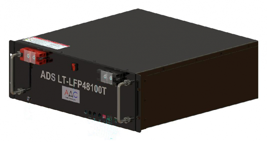
  • I have battery ADS LT-LFP 48100Т (5kW 48V 100Ah LiFePo) from local Ukrainian vendor ADS. This battery built on prismatic cells and JK Inverter BMS PB1A16S10P (Hardware Ver: V15A, Firmware Ver: V15.27).
    Picture 7. ADS LT-LFP 48100T battery
    Picture 8. Battery JK BMS data
  • Install JK BMS app on smartphone/tablet and connect to the inverter via Bluetooth. Default password is "1234".
  • Prepare cable to connect battery and inverter. You need Type A cable to connect battery BMS to inverter VE.Can port (VE.Can to CAN-bus BMS cables manual).
    FunctionVictron VE.Can sideBattery side
    GNDPin 3Pin 6
    CAN-LPin 8Pin 5
    CAN-HPin 7Pin 4
    Table 1. Cable Type A pinout scheme.
  • Open inverter remote console. Press "Enter" button, go to "Settings" -> "Services" -> "VE.Can port" -> "CAN-bus profile" and select option "CAN-bus BMS LV (500 kbit/s)".
    • Open JK BMS app, go to "Settings" page, click on "Verify PWD" and enter Bluetooth password once again (default is 1234), click "Advanced Settings". Scroll down and click on the option "CAN Protocol No.:", select option "004 - Victron_CANbus_BMS_protocol_20170717", click "Ok" to set this option.
      Picture 9. JK BMS CAN protocol for Victron Multiplus II GX
  • Connect battery and inverter with prepared cable.
    Put the VE.Can RJ45 terminator to the second VE.Can port in the inverter.
    Be aware that cable is not symmetrical. So you must connect battery cable side to the battery and VE.Can cable side to the VE.Can port in inverter.
    Picture 10. Inverter VE.Can ports
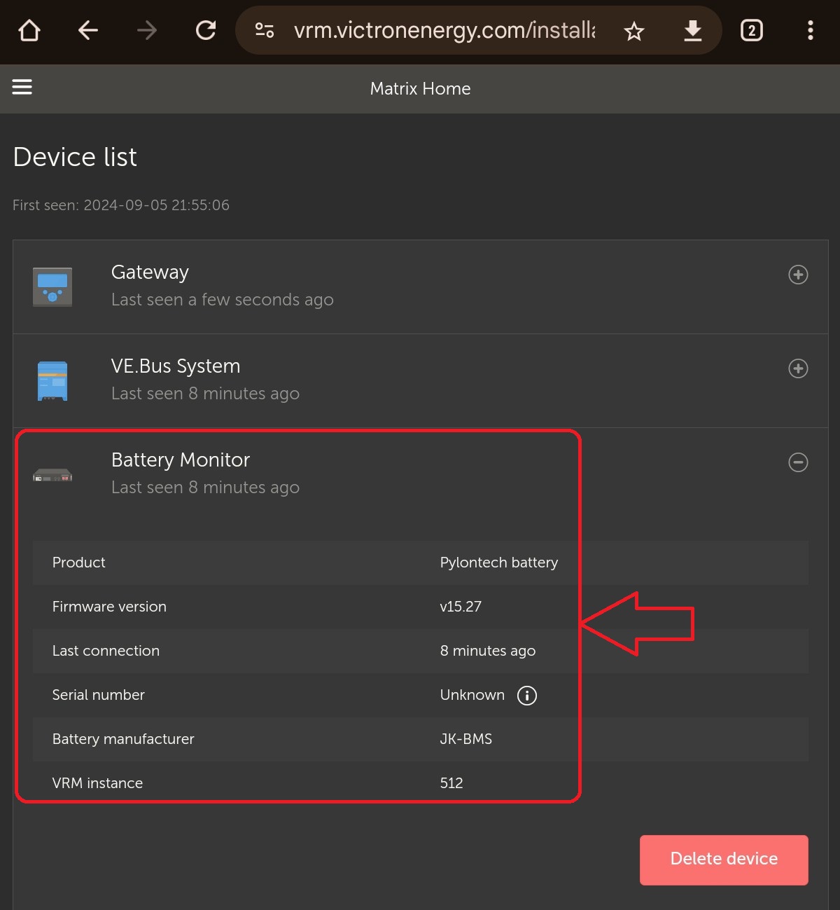
  • If connection established successfully you can see new device "JK-BMS" on inverter Remote Console.
    Picture 11. JK BMS in Inverter Remote Console
    Also battery will show in VRM portal.
    Picture 12. Battery on VRM Dashboard
    Picture 13. Battery in VRM Device List

Tuesday, February 27, 2024

Brocade FC switch: Unable to collect ConfigUpload or Supportsave via SCP and SFTP (scp failed)

 Situation:

  • host with OS Linux (RHEL, Rocky Linux etc.)
  • host can access to switch
  • no firewall blocks between switch and host
  • network admin open access from switch to host on 22 port
  • but configUpload returns error: scp failed

 SCP Example:
switch:admin> configupload
Protocol (scp, ftp, sftp, local) [ftp]: scp
Do you want to continue with CRA (Y/N) [N]: y
Server Name or IP Address [host]: 10.0.0.1
User Name [user]: admin
Path/Filename [<home dir>/config.txt]: /configupload.scp
Section (all|chassis|switch [all]): switch
lost connection
configUpload not permitted (scp failed).
Terminated

 Resolution:

Clear all known hosts keys on switch:
sshutil delknownhost -all

Found this on Dell support knowledge base:
Connectrix B-Series:Unable to collect ConfigUpload or Supportsave via SCP and SFTP

Monday, October 30, 2023

Start GUI application from Windows on remote Linux server with Xming

  1. Start Xming.
  2. Set "Enable X11 forwarding" in Putty configuration (Connection -> SSH -> X11).
  3. Login to remote Linux server with SSH via Putty.
  4. Start GUI application with logged user credentials.
  5. If you need to start GUI application with root credentials:
    • run "sudo su -"
    • run commands:
      $ chmod a+r /home/<user_login>/.Xauthority
      $ export DISPLAY=localhost:10.0
      $ export XAUTHORITY=/home/<user_login>/.Xauthority

Monday, February 6, 2023

Update of IBM Spectrum Protect for Virtual Environment (VMware) finished with Java error "java/lang/OutOfMemoryError"

 If update of IBM Spectrum Protect for Virtual Environment (VMware) finished with Java error "java/lang/OutOfMemoryError" and you see errors like this:

JVMDUMP032I JVM requested Heap dump using '/tmp/install.dir.1556855/heapdump.20230206.143627.1556855.0011.phd' in response to an event
JVMDUMP010I Heap dump written to /tmp/install.dir.1556855/heapdump.20230206.143627.1556855.0011.phd
JVMDUMP032I JVM requested Java dump using '/tmp/install.dir.1556855/javacore.20230206.143627.1556855.0012.txt' in response to an event
JVMDUMP010I Java dump written to /tmp/install.dir.1556855/javacore.20230206.143627.1556855.0012.txt
JVMDUMP032I JVM requested Snap dump using '/tmp/install.dir.1556855/Snap.20230206.143627.1556855.0013.trc' in response to an event
JVMDUMP010I Snap dump written to /tmp/install.dir.1556855/Snap.20230206.143627.1556855.0013.trc
JVMDUMP013I Processed dump event "systhrow", detail "java/lang/OutOfMemoryError".

Try to start install process with the option "-jvmxmx 12g":

./installer-Linux.bin -jvmxmx 12g

Wednesday, December 14, 2022

IBM Storwize/FlashSystem/SVC CLI examples, tips and tricks

  •  List FRU part number for specific Tier drives:
    svcinfo lsdrive -nohdr |while read id status use tech_type capacity;do if [[ $tech_type == "tier0_flash" ]];then lsdrive $id | while read idd value;do if [[ $idd == "FRU_part_number" ]];then echo $id";"$tech_type";"$value;fi;done;fi;done

Friday, July 8, 2022

Veeam Types of Backup Files

 Veeam Types of Backup Files

Source:
Veeam Agent Types of Backup Files

Veeam for Vmware vSphere Backup Chain 

List of Veeam file extensions


File typeVeeam ComponentDescription
VBK
VBR for VMware
VBR for Hyper-V
Veeam Agent
Full backup file
VIB
VBR for VMware
VBR for Hyper-V
Veeam Agent
Incremental backup file
Forever forward incremental (FFI) or Forward incremental (FI) for VBR for VMware or Hyper-V
VBM
VBR for VMware
VBR for Hyper-V
Veeam Agent
Backup metadata files that store information about the backup job, VMs processed by the backup job, number and structure of backup files, restore points, and so on. Metadata files facilitate import of backups, backup mapping and other operations.
VSB
VBR for VMware
VBR for Hyper-V
Virtual synthetic backup files used for generation of virtual full backups on tapes. For more information, see Virtual Full Backup.
VLB
VBR for VMware
VBR for Hyper-V
Veeam Agent
MS SQL transaction log backups
Oracle archived log backups
VLM
VBR for VMware
VBR for Hyper-V
Veeam Agent
MS SQL transaction log backups
Oracle archived log backups
VSM
VBR for VMware
VBR for Hyper-V
Veeam Agent
MS SQL transaction log backups
Oracle archived log backups
VOM
VBR for VMware
VBR for Hyper-V
Veeam Agent
MS SQL transaction log backups
Oracle archived log backups
VRB
VBR for VMware
VBR for Hyper-V
Reverse incremental (RI) backup file

Keep in mind that Veeam Agent creates VLM files only in backup chains started in Veeam Agent for Microsoft Windows 5.0 and later. If you upgrade Veeam Agent and continue the backup chain that was started in the earlier Veeam Agent version, Veeam Agent will not create VLM files in this backup chain.

Monday, June 13, 2022

Как отключить рекламу в uTorrent

  1. Options -> Preferences -> Advanced (Настройки -> Настройки Программы -> Дополнительно)
  2. Установить в "false" параметры
    • offers.featured_content_badge_enabled
    • offers.featured_content_notifications_enabled
    • offers.featured_content_rss_enabled
    • offers.featured_content_rss_randomize
    • offers.left_rail_offer_enabled
    • offers.sponsored_torrent_offer_enabled
    • gui.show_plus_upsell
    • bt.enable_pulse

Thursday, April 7, 2022

Storage rule replication hang for a long time. No network activity

Situation.

Storage rule replication process shows as active process in the source and target TSM server. But there is no network activity and data is not transferring between TSM servers.

Content.

Open file dsmffdc.log on the source TSM server and find lines with the pattern "[ FFDC_REPLICATIOIN ]". You can find lines something like this:

[04-06-2022 02:29:31.066][ FFDC_REPLICATION ]: (smtrans.c:11224) Cannot send DistDedupChunkVerb - termReason 1 indicated for session TARGET-TSM-01(89625).~

Resolution.

Cancel hang replication process and restart it again.

Saturday, January 30, 2016

Загрузка 100% SSD диска в Windows 10.

     Поставил себе SSD диск Kingston HyperX Savage 240GB. Установил на него с нуля Windows 10. И был очень неприятно удивлен, когда периодически Task Manager показывал загрузку SSD в 100% и вся работа замирала на минуту-две. Начал искать откуда эта проблема и как ее лечить.

Вот возможные варианты исправления данной проблемы (они описаны в хронологическом порядке как я их пробовал применять):
  • Проверить и, если нужно, обновить прошивки на BIOS и SSD диск.
  • Отключить в Windows режим Message Signaled Interrupt (MSI)
    Task Manager might show 100% disk utilization on Windows 10 devices with Message Signaled Interrupt (MSI) mode enabled
    Сначала мне пару раз помогало отключение MSI. Но после очередного обновления Windows 10 на новый билд это решение уже не сработало.
  • Отключить кэш на запись для SSD.
    Это делается в Device Manager'е. Может не помочь, но это, в принципе, для SSD полезная настройка.
  • Проверить и, если нужно, обновить драйвер на SATA контроллер.
    Когда у меня не сработало решение с отключением MSI, я обнаружил, что после обновления Windows 10 на новый билд драйвер на SATA контроллер стоит стандартный от Microsoft, а у меня материнская плата на чипсете от AMD. Поэтому я нашел последний драйвер на SATA контроллер (на сайте AMD Radeon Software Crimson Edition Graphics Driver Installer for Windows 10 64-Bit находится на вкладке Optional Downloads) и руками обновил его на последнюю версию от AMD. И, наконец-то, у меня пропали замирания системы из-за 100% загрузки SSD.

Tuesday, October 6, 2015

Vmware. Задание policy path для LUN-а в ESXi

​
Нужна всего пара команд.
Можно делать через vSphere CLI или напрямую через SSH консоль.
  1. Вывод списка подключенных LUN'ов (device)
    esxcli nmp device list
    Например:
    naa.600a0b80003ac474000006884b9ef497
        Device Display Name: DS3400_SQLTest
        Storage Array Type: VMW_SATP_LSI
        Storage Array Type Device Config: SATP VMW_SATP_LSI does not support device configuration.
        Path Selection Policy: VMW_PSP_MRU
        Path Selection Policy Device Config: Current Path=vmhba2:C0:T1:L20
        Working Paths: vmhba2:C0:T1:L20
  2. Задание path policy для LUN'а.
    Выбираем нужный LUN и берем его device id, например naa.600a0b80003ac474000006884b9ef497
    Выполняем команду
    esxcli nmp device setpolicy --psp VMW_PSP_MRU --device naa.600a0b80003ac474000006884b9ef497
    Здесь мы задали для девайса naa.600a0b80003ac474000006884b9ef497 path policy VMW_PSP_MRU, т.е. политику наиболее часто используемого пути.
Подробности читать в мауале vSphere Command-Line Interface Installation and Reference Guide стр. 85.
Читать до полного просветления и НЕ БАЛОВАТЬСЯ этой настройкой.
Один раз сделал - и НЕ ТРОГАЙ без ОЧЕНЬ веской причины!

Vmware. Flex x240. Первоначальная настройка UEFI для VMware ESXi

​Для VMware ESXi рекомендуется такие настройки UEFI:
  • System Settings
    • Operating Modes
      • Choose Operating Mode - Custom
      • Power/Performance Bias - OS Controlled
      • Memory Power Management - Disable
      • Memory Speed - Max Performance
      • Turbo Mode - Enable
      • CPU C-States - Enable
      • C1 Enhanced Mode - Enable
      • QPI Link Frequency - Max Performance
    • Power
      • Workload Configuration - Balanced
      • Active Energy Manager - Capping Enabled
  • Для сетевого адаптера включить поддержку SR-IOV.

Vmware. Windows 2008-2012. На виртуалке появляется лишний дуплицирующий IP адрес

​На виртуалке с Windows 2008, 2012 после настройки статического IP адреса может появится лишний дуплицирующий IP адрес вида 169.254.x.x.
Решение из статьи VMwareKB 1028373 False duplicate IP address detected on Microsoft Windows Vista and later virtual machines on ESX/ESXi when using Cisco devices on the environment (1028373)
  • Выключить виртуалку.
  • Перенастроить сетевой адаптер на vSwitch без рабочего аплинка.
  • Включить виртуалку и залогиниться на нее.
  • Зайти в реестр и задать значение параметра ArpRetryCount = 0 в ветке реестра
    HKEY_LOCAL_MACHINE\SYSTEM\CurrentControlSet\Services\Tcpip\Parameters
  • Выключить виртуалку.
  • Перенастроить сеть на vSwitch с рабочим аплинком.
  • Включить виртуалку.
Альтернативное решение - отключить gratuitous ARP на коммутаторах Cisco:
# no ip gratuitous-arps

Vmware. Эталонный образ сервера Windows Server

​
  1. Create virtual machine
    • 4 CPU cores (default)
    • 4 GB RAM (default)
    • 40GB HDD SCSI (0;0) Thin Provision
    • SCSI controller LSI Logic SAS. For VM with high IO load use VMware Paravirtualization (VM PVSCSI)
    • Virtual Machine version 8 (default)
    • use VMXNET3 network adapter
    • Use EFI boot firmware
  2. Install Windows Server 2012
  3. Windows settings
    • install VMware Tools
    • open Control Panel
      • check Date and Time settings
      • check Language Settings (ENG - UKR - RUS)
      • Power Options
        • set High Performance
        • set Turn off the display - Never
      • Region settings
        • check settings
        • Advanced - Copy Settings... - copy settings to welcome screen and New  user account
      • System - Change settings
        • Allow remote connections to this computer
        • set computer name
        • temporary join to Active Directory domain for Windows Update. After updating Windows - remove server form Active Directory
        • Advanced - Startup and Recovery settings - use Small memory dump
    • open cmd with Admin rights and run (it disables hibernation): powercfg -h off
    • select disk C: properties - uncheck Allow files on this drive to have contents indexed in addition to file properties - Apply to C:\ only
    • enable File and Printer Sharing in Windows Firewall for Domain network
    • after installing all Windows Updates
      • cleanup system
        to analyze system run
        dism /Online /Cleanup-Image /AnalyzeComponentStore

        to cleanup system run
        dism /Online /Cleanup-Image /StartComponentCleanup
    • after cleanup system
      • disable swap file and reboot
      • defragment system disk C:
      • enable swap file and reboot
  4. В конце можно финализировать образ
    sysprep /generalize /oobe /shutdown

http://blog.solori.net/2010/09/30/in-the-lab-windows-server-2008-r2-template-for-vmware/
http://www.mikes.eu/index.php/how-to/284-how-to-build-a-windows-2008-r2-vmware-template-2.html
http://willcode4foodblog.wordpress.com/2013/03/22/creating-a-server-2012-golden-image-with-sysprep-and-vmware-workstation-part-2-of-2/

VCSA 51. Интеграция с Active Directory

​
  1. In the "VMware vCenter Server Appliance" web site got to vCenter Server -> Authentication
    • Check "Active Directory Enabled"
    • Eneter values to fields:
      • Domain - domain name.
      • Administrator user - user principal name (UPN) with administrative rights in the domain.
      • Administrator password - password
    • For example:
  2. Go to vSphere Web Client with root account
    • Go to Administration -> Sign-On and Discovery -> Configuration -> Identity Sources
    • Click the + (green) symbol (Add Identity Source) and fill in the required information:
      • Name - Anything you want to refer to this Identity source as (typically domain name)
      • Primary Server URL: ldap://<domain server FQDN>
      • Secondary Server URL: <optional>
      • Base DN for users: distinguished name (DN) of object unit (OU) with users
      • Domain Name: <Domain Name>
      • Domain alias: <NetBIOS domain name>.
        WARNING!!! You must fill out this field. If you dont - you can't login to vSphere Web Client with AD login <domain>\<username> and option "Use Windows session authentication" don't work.
      • Base DN for groups: distinguished name (DN) of object unit (OU) with groups
      • Authentication Type: (How you want to authenticate the initial connection to your domain)
    • For example:
      • Name - MyDomain
      • Primary Server URL: ldap://mydom-dc1.com
      • Secondary Server URL: ldap://mydom-dc2.com
      • Base DN for users: OU=Users,OU=IT,DC=mydomain,DC=com
      • Domain Name: mydomain.com
      • Domain alias: mydomain
      • Base DN for groups: OU=Groups,OU=IT,DC=mydomain,DC=com
      • Authentication Type: Reuse Session
    • Select your AD server URL and click on the blue dot with an arrow ("Add to default domains").
      WARNING!!! When your domain appears in default domains list click on the blue disk icon to save your change, otherwise you will be wondering why it is not working as expected.
    • Go to Administration -> Access -> SSO Users and Groups -> Groups
      • Select internal group __Administrators__
      • Click "Add Principals"
      • Find user or group in AD domain and add to group __Administrators__
More information can find in this articles:
VMware vCenter 5.1 Installation: Part 9 (Optional SSO Configuration)
Unable to login to vCenter Server after upgrading to vCenter Server 5.1

Vmware. Linux VM. Решение проблемы - разрешение экрана при установке Linux слишком мало

​Решение для Oracle Linux, но, наверно, сработает и для других
  • На экране установки выбираем пункт "Troubleshooting".
  • На следующем экране выбираем пункт "Install Oracle Linux 7.0 in basic graphics mode" и жмем клавишу Tab.
  • Далее возможны три варианта:
    • изменяем параметр xdriver=vesa на xdriver=vmware и жмем Enter.
      Если не срабатывает пробуем следующий вариант.
    • изменяем параметр xdriver=vesa на xdriver=vmware, добавляем параметр inst.resolution=1280x800 и жмем Enter.
      Если не срабатывает пробуем следующий вариант.
    • оставляем параметр xdriver=vesa без изменений, добавляем параметр inst.resolution=1280x800 и жмем Enter.

Vmware. How-to enable SSH for ESXi

​
  1. Go to the ESXi console and press alt+F1
  2. Type: unsupported
  3. Enter the root password
  4. At the prompt type “vi /etc/inetd.conf”
  5. Look for the line that starts with “#ssh” (you can search with pressing “/”)
  6. Remove the “#” (press the “x” if the cursor is on the character)
  7. Save “/etc/inetd.conf” by typing “:wq!”
  8. Reboot server or restart inetd service with command kill -HUP `cat /var/run/inetd.pid`;
Source: link1, link2

TSM Server. Как удалить определенную Legacy резервную копию с сервера

​Официально есть команда по удалению резервных копий. Но она работает только для VSS резервных копий.
Legacy резервные копии официально рекомендуется проводить по цепочке: active backup - inactive backup - и потом согласно политик inactive backup-ы будут удаляться.
Есть ещё один способ, но по-моему не официальный (в смысле если что набедокурите мы ответсвенности не несём, так что будьте внимательны и аккуратны) через консоль администирования TSM (dsmadmc).
Определяете объёкты, которые вам нужно удалить
select filespace_name,hl_name,ll_name,state,object_id from backups where node_name='<node_name_for_the_sql_backup>' ;
node_name_for_the_sql_backup - большими символами.
Удаляете выбраные объекты командой, одна команда - один объёкт:
delete object <object_id>

TSM Server. Сброс пароля для пользователя admin в Tivoli Storage Manager server

​
  1. Останавливаем службу TSM server
    service tsminst1_dsmserv.rc stop
    или
    kill `cut -sd " " -f 4 /tsm/tsminst1/dsmserv.v6lock`
  2. Заходим на сервер под пользователем, под которым запускается сервер TSM (tsminst1)
  3. Запускаем сервер, но не как службу, а как обычную программу (foreground)
    Starting the server from the user ID that owns the server instance
    • Перед запуском сервера запускаем db2profile
      ./home/tsminst1/sqllib/db2profile
    • Переходим в рабочий каталог сервера TSM
      cd /tsm/tsminst1
    • Запускаем сервер командой
      /opt/tivoli/tsm/server/bin/dsmserv
  4. И мы сразу попадаем в консоль сервера TSM
  5. Для сброса пароля выполняем команду UPADTE ADMIN
    UPDATE ADMIN admin <new_password>
  6. Все. Можно останавливать сервер и перезапускать его как обычно.
    Я это попробовал сделать без перезагрузки сервера (команда HALT - остановить TSM сервер, service tsminst1_dsmserv.rc start - запуск службы сервера). Но что-то пошло не так и выдавало ошибки. После перезагрузки всего сервера все запустилось норм.